light physic chapter class 10 full solution and notes
INTRODUCTION
We see a variety of objects in the world around us. However, we are unable to see anything in a dark room. On lighting up the room, things become visible. What makes things visible? During the day, the sunlight helps us to see objects. An object reflects light that falls on it. This reflected light, when received by our eyes, enables us to see things. We are able to see through a transparent medium as light is transmitted through it. There are a number of common wonderful phenomena associated with light such as image formation by mirrors, the twinkling of stars, the beautiful colours of a rainbow, bending of light by a medium and so on. A study of the properties of light helps us to explore them. By observing the common optical phenomena around us, we may conclude that light seems to travel in straight lines. The fact that a small source of light casts a sharp shadow of an opaque object points to this straight-line path of light, usually indicated as a ray of light. The objects like the sun, other stars, electric bulbs, tube-light, torch, candle and fire, etc., which emit their own light are called luminous objects. The objects which do not emit light themselves but only reflect (or scatter) the light which falls on them, are called non-luminous objects.
If an opaque object on the path of light becomes very small, light has a tendency to bend around it and not walk in a straight line – an effect known as the diffraction of light. Nature of Light
There are two theories about the nature of light : wave theory of light and particle theory of light.
According to wave theory : Light consists of electromagnetic waves which do not require a material medium (like solid, liquid or gas) for their propagation. The wavelength of visible light waves is very small (being only about m to m). The speed of light waves is very high (being about metres per second in vacuum).
According to particle theory : Light is composed of particles which travel in a straight line at very high speed. The elementary particle that defines light is the photon.
Some of the phenomena of light can be explained only if light is considered to be made up of waves whereas others can be explained only if light is thought to be made up of particles. For example, the phenomena of diffraction (bending of light around the corners of tiny objects), interference and polarization of light can only be explained if light is considered to be of wave nature. The particle theory of light cannot explain these phenomena. On the other hand, the phenomena of reflection and refraction of light, and casting of shadows of objects by light, can be explained only if light is thought to be made of particles. Wave theory of light cannot explain these phenomena. Thus, there is evidence for the wave nature of light as well as for particle nature of light.
Experiments over the past hundred years or so have demonstrated that light has a dual nature (double nature): light exhibits the properties of both waves and particles (depending on the situation it is in). The modern theory of light called Quantum Theory of Light combines both the wave and particle models of light.
When light falls on the surface of an object, some of it is sent back. The process of sending back the light rays which fall on the surface of an object, is called Reflection of Light. Let us recall the laws of reflection: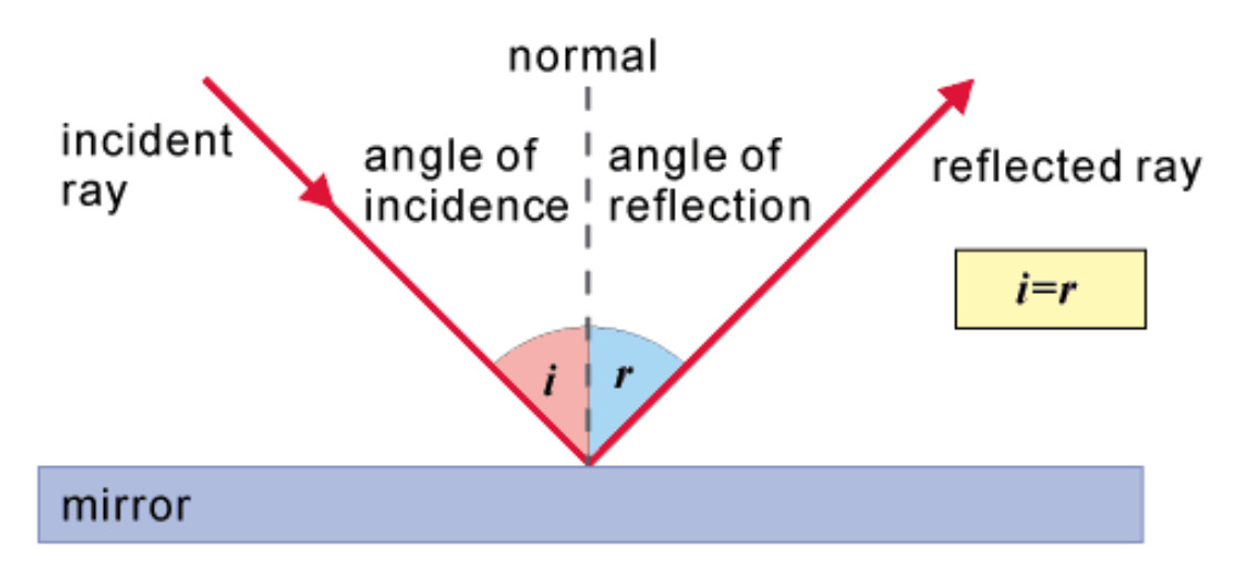
(i) The angle of incidence is equal to the angle of reflection,and
(ii) The incident ray,the normal to the mirror at the point of incidence and the reflected ray,all lie in the same plane.
These laws of reflection are applicable to all types of reflecting surfaces,including spherical surfaces. The objects having polished, shining surfaces reflect more light than objects having unpolished, dull surfaces.
Silver metal is one of the best reflectors of light. For example, a polished block of silver metal reflects almost all the light falling on it and does not transmit any light through it. But the surface of silver metal is easily scratched and soon becomes rough. So, ordinary mirrors are made by depositing a thin layer of silver metal on the back side of a plane glass sheet. The silver layer is then protected by a coat of red paint. The reflection of light in a plane mirror (or any other mirror) takes place at the silver surface in it. Thus, a plane mirror is a thin, flat and smooth sheet of glass having a shining coating of silver metal on one side.
Reflection is of two types:
1.Regular Reflection: When the reflecting surface is smooth and well polished,the parallel rays falling on it are reflected parallel to one another,as shown in Figure, i.e., the reflected light goes in one particular direction. This is regular reflection.The smooth and well polished surface from which light suffers regular reflection is called a mirror. Silver metal is one of the best reflectors of light. So,ordinary mirrors are made by depositing a thin layer of silver metal on one side of a plane glass sheet.The silver layer is protected by coat of red paint on the backside of the mirror.The reflection of light in a mirror takes place at the silver surface.A plane mirror is represented by a straight line, with a light shade showing back of the mirror.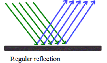
2. Irregular reflection: When the reflecting surface is rough, the parallel rays falling on it are reflected in different directions,as shown in Figure. Such a reflection is known as diffuse reflection or irregular reflection or even scattering of light.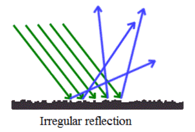
Image formed by a plane mirror is always virtual and erect. The size of the image is equal to that of the object. The image formed is as far behind the mirror as the object is in front of it. Further, the image is laterally inverted. The curved surface of a shining spoon could be considered as a curved mirror. The most commonly used type of curved mirror is the spherical mirror. The reflecting surface of such mirrors can be considered to form a part of the surface of a sphere. Such mirrors, whose reflecting surfaces are spherical, are called spherical mirrors.
The reflecting surface of a spherical mirror may be curved inwards or outwards. A spherical mirror, whose reflecting surface is curved inwards, that is, faces towards the centre of the sphere, is called a concave mirror. A spherical mirror whose reflecting surface is curved outwards, is called a convex mirror. The schematic representation of these mirrors is shown in Figure.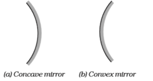
The back part of the mirrors in these diagrams is shaded. The surface of the spoon curved inwards can be approximated to a concave mirror and the surface of the spoon bulged outwards can be approximated to a convex mirror. Some of the important terms which are commonly used about spherical mirrors or it can be called as nomenclature of the mirrors are:
- The diameter of the reflecting surface of spherical mirror is called its aperture. Mirrors whose aperture is much smaller than its radius of curvature, we use R=2f.
- The centre of the reflecting surface of a spherical mirror is a point called the pole. It lies on the surface of the mirror. The pole is usually represented by the letter P.
- The reflecting surface of a spherical mirror forms a part of a sphere. This sphere has a centre. This point is called the centre of curvature of the spherical mirror. It is represented by the letter C. The centre of curvature is not a part of the mirror. It lies outside its reflecting surface. The centre of curvature of a concave mirror lies in front of it. However, it lies behind the mirror in case of a convex mirror (Fig. 2 (a) and (b)).
- The radius of the sphere of which the reflecting surface of a spherical mirror forms a part, is called the radius of curvature of the mirror. It is represented by the letter R. The distance PC in the Fig. 2 is equal to the radius of curvature.
- A straight line passing through the pole and the centre of curvature of a spherical mirror is called the principal axis. Principal axis is normal to the mirror at its pole.
- A paraxial ray is a ray which makes a small angle (θ) to the optical axis of the system, and lies close to the axis throughout the system.
- Marginal rays are the rays which pass through the maximum aperture of the spherical mirror.
When a concave mirror is holded in a hand and its reflecting surface is directed towards the sun, and the reflected light by the mirror is directed on the sheet of paper held close to the mirror, then when paper and mirror is held in the same position where a sharp, bright spot of light is observed. The paper at first begins to burn producing smoke. Eventually it may even catch fire. Why does it burn? The light from the Sun is converged at a point, as a sharp, bright spot by the mirror. In fact, this spot of light is the image of the Sun on the sheet of paper. This point is the focus of the concave mirror. The heat produced due to the concentration of sunlight ignites the paper. The distance of this image from the position of the mirror gives the approximate value of focal length of the mirror.
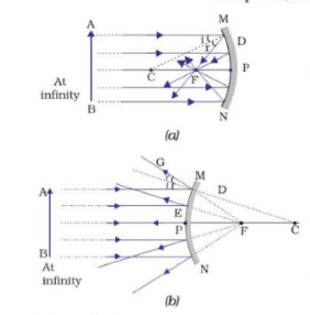 Figure 2: (a) Concave Mirror (b) Convex Mirror
According to Fig. 2(a), a number of rays parallel to the principal axis are falling on a concave mirror. The reflected rays are all meeting/intersecting at a point on the principal axis of the mirror. This point is called the principal focus of the concave mirror. Similarly, Fig. 2 (b). The reflected rays appear to come from a point on the principal axis in the convex mirror. This point is called the principal focus of the convex mirror. The principal focus is represented by the letter F. The distance between the pole and the principal focus of a spherical mirror is called the focal length. It is represented by the letter .
The reflecting surface of a spherical mirror is by-and-large spherical. The surface, then, has a circular outline. The diameter of the reflecting surface of a spherical mirror is called its aperture. For spherical mirrors of small apertures, the radius of curvature is found to be equal to twice the focal length. We put this as . This implies that the principal focus of a spherical mirror lies midway between the pole and centre of curvature.
Image Formation by Spherical Mirrors
The nature, position and size of the image formed by a concave mirror depends on the position of the object in relation to points P, F and C. The image formed is real for some positions of the object. It is found to be a virtual image for a certain other position. The image is either magnified, reduced or has the same size, depending on the position of the object. A summary of image formation by a concave mirror is given in Table 1.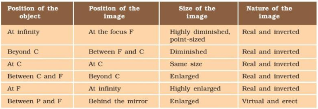
Representation of Images Formed by Spherical Mirrors Using Ray Diagrams
Consider an extended object, of finite size, placed in front of a spherical mirror. Each small portion of the extended object acts like a point source. An infinite number of rays originate from each of these points. To construct the ray diagrams, in order to locate the image of an object, an arbitrarily large number of rays emanating from a point could be considered. However, it is more convenient to consider only two rays, for the sake of clarity of the ray diagram. These rays are so chosen that it is easy to know their directions after reflection from the mirror. The intersection of at least two reflected rays give the position of image of the point object. Any two of the following rays can be considered for locating the image. Let us take a look at some cases:
(i) A ray parallel to the principal axis, after reflection, will pass through the principal focus in case of a concave mirror or appear to diverge from the principal focus in case of a convex mirror. This is illustrated in Fig. 3 (a) and (b).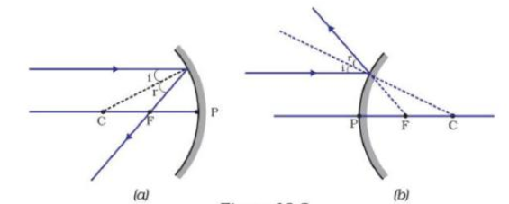
(ii) A ray passing through the principal focus of a concave mirror or a ray which is directed towards the principal focus of a convex mirror, after reflection, will emerge parallel to the principal axis. This is illustrated in Fig. 4 (a) and (b).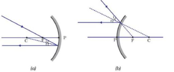
(iii) A ray passing through the centre of curvature of a concave mirror or directed in the direction of the centre of curvature of a convex mirror, after reflection, is reflected back along the same path. This is illustrated in Fig. 5 (a) and (b). The light rays come back along the same path because the incident rays fall on the mirror along the normal to the reflecting surface.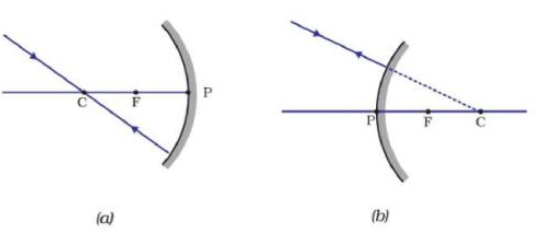
(iv) A ray incident obliquely to the principal axis, towards a point P (pole of the mirror), on the concave mirror [Fig. 6 (a)] or a convex mirror [Fig. 6 (b)], is reflected obliquely. The incident and reflected rays follow the laws of reflection at the point of incidence (point P), making equal angles with the principal axis.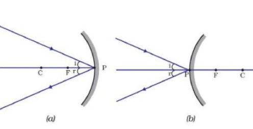
Remember that in all the above cases the laws of reflection are followed. At the point of incidence, the incident ray is reflected in such a way that the angle of reflection equals the angle of incidence.
(a) Image Formation by Concave Mirror
Figure 7 illustrates the ray diagrams for the formation of images by a concave mirror for various positions of the object.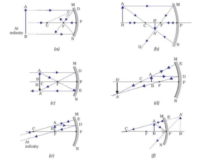
Applications or Uses of Concave Mirrors
- Concave mirrors are commonly used in torches, search-lights and vehicle headlights to get powerful parallel beams of light.
- They are often used as shaving mirrors to see a larger image of the face.
- The dentists use concave mirrors to see large images of the teeth of patients.
- Large concave mirrors are used to concentrate sunlight to produce heat in solar furnaces.
(b) Image formation by a Convex Mirror
We consider two positions of the object for studying the image formed by a convex mirror. First is when the object is at infinity and the second position is when the object is at a finite distance from the mirror. The ray diagrams for the formation of image by a convex mirror for these two positions of the object are shown in Fig. 8 (a) and (b), respectively.
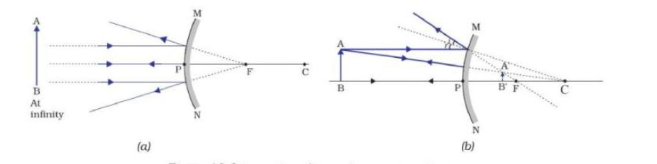
The results are summarised in Table 10.2.
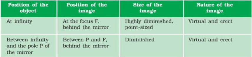
A small convex mirror is used to see a full-length image of a tall building/tree. One such mirror is fitted in a wall of Agra Fort facing Taj Mahal.
Application or Use of Convex Mirrors
Convex mirrors are commonly used as rear-view (wing) mirrors in vehicles. These mirrors are fitted on the sides of the vehicle, enabling the driver to see traffic behind him/her to facilitate safe driving. Convex mirrors are preferred because they always give an erect, though diminished, image. Also, they have a wider field of view as they are curved outwards. Thus, convex mirrors enable the driver to view much larger areas than would be possible with a plane mirror. Sign Convention for Reflection by Spherical Mirrors
While dealing with the reflection of light by spherical mirrors, follow a set of sign conventions called the New Cartesian Sign Convention. In this convention, the pole (P) of the mirror is taken as the origin (Fig. 9). The principal axis of the mirror is taken as the x-axis (X’X) of the coordinate system.
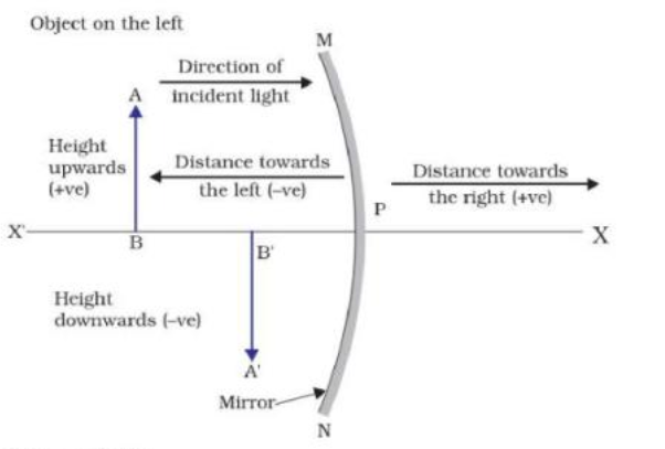
The conventions are as follows:– (i) The object is always placed to the left of the mirror. This implies that the light from the object falls on the mirror from the left-hand side. (ii) All distances parallel to the principal axis are measured from the pole of the mirror. (iii) All the distances measured to the right of the origin (along -axis) are taken as positive while those measured to the left of the origin (along -axis) are taken as negative. (iv) Distances measured perpendicular to and above the principal axis (along -axis) are taken as positive. (v) Distances measured perpendicular to and below the principal axis (along -axis) are taken as negative. Mirror Formula and Magnification
In a spherical mirror, the distance of the object from its pole is called the object distance . The distance of the image from the pole of the mirror is called the image distance . The distance of the principal focus from the pole is called the focal length . There is a relationship between these three quantities given by the mirror formula which is expressed as
.........(1)
This formula is valid in all situations for all spherical mirrors for all positions of the object.
Magnification
Magnification produced by a spherical mirror gives the relative extent to which the image of an object is magnified with respect to the object size. It is expressed as the ratio of the height of the image to the height of the object. It is usually represented by the letter . If is the height of the object and is the height of the image, then the magnification m produced by a spherical mirror is given by:
Height of the image(h’)/Height of the object (h)
...............(2)
The magnification is also related to the object distance and image distance . It can be expressed as:
Magnification .........................(3)
The height of the object is taken to be positive as the object is usually placed above the principal axis. The height of the image should be taken as positive for virtual images. However, it is to be taken as negative for real images. A negative sign in the value of the magnification indicates that the image is real. A positive sign in the value of the magnification indicates that the image is virtual.
Find the focal length of a convex mirror of radius of curvature 1 m.
radius of curvature,
As ,
A convex mirror used for rear-view on an automobile has a radius of curvature of 3.00 m. If a bus is located at 5.00 m from this mirror, find the position, nature and size of the image.
Object-distance, ,
Image-distance,
Height of the image,
Focal length, (as the principal focus of a convex mirror is behind the mirror)
Since
or,
The image is 1.15 m at the back of the mirror.
Magnification,
The image is virtual, erect and smaller in size by a factor of 0.23.
An object, 4.0 cm in size, is placed at 25.0 cm in front of a concave mirror of focal length 15.0 cm. At what distance from the mirror should a screen be placed in order to obtain a sharp image? Find the nature and the size of the image.
Object-distance, ,
Focal length, ,
Image-distance,
Image-size,
or,
or, or,
The screen should be placed at 37.5 cm in front of the mirror. The image is real.
Also, magnification,
or,
Height of the image, . The image is inverted and enlarged.
When a spherical mirror is held towards the sun and its sharp image is formed on a piece of carbon paper for some time, a hole is burnt in the carbon paper.
(a) What is the nature of spherical mirror ?
(b) Why is a hole brnt in the carbon paper ?
( c) At which point of the spherical mirror the carbon paper is placed ?
(d) What name is given to the distance between spherical mirror and carbon paper ? ( e) What is the advantage of using a carbon paper rather then a white paper ?
The linear magnification of a convex mirror of focal length 15 cm is . What is the distance of the object from the focus of the mirror ?
From
From
u = -30cm.
This is the distance of the object from pole of the mirror i.e. . Distance of object from focus of mirror

Comments
Post a Comment
Ask me anything here...